

Подробную информацию о продукте см. в характеристиках.
Q4004L4TP Product Overview
Introduction
The Q4004L4TP is a semiconductor device belonging to the category of silicon-controlled rectifiers (SCRs). This component is widely used in various electronic applications due to its unique characteristics and functional features. In this entry, we will provide an overview of the Q4004L4TP, including its basic information, specifications, pin configuration, functional features, advantages and disadvantages, working principles, application field plans, and alternative models.
Basic Information Overview
- Category: Semiconductor Device
- Use: Power Control and Regulation
- Characteristics: High Voltage and Current Handling Capabilities
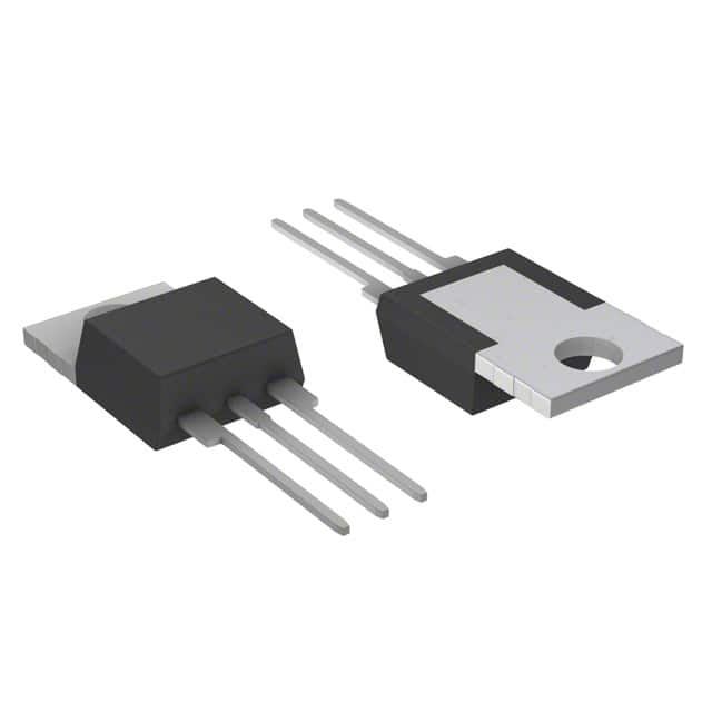
- Package: TO-220AB
- Essence: Silicon-Controlled Rectifier
- Packaging/Quantity: Individual Component
Specifications
- Voltage Rating: 400V
- Current Rating: 4A
- Gate Trigger Current: 200µA
- Operating Temperature Range: -40°C to 125°C
- Mounting Type: Through Hole
Detailed Pin Configuration
The Q4004L4TP has a standard TO-220AB package with three leads: 1. Anode (A) 2. Cathode (K) 3. Gate (G)
Functional Features
- High Voltage Capability: The Q4004L4TP can handle high voltage levels, making it suitable for power control applications.
- Gate Triggering: It can be easily triggered by applying a small current to the gate terminal, allowing precise control over the switching operation.
- Reliability: With its robust design, the Q4004L4TP offers high reliability in demanding environments.
Advantages and Disadvantages
Advantages
- High voltage and current handling capabilities
- Precise gate triggering for accurate control
- Robust and reliable performance
Disadvantages
- Sensitive to voltage and current spikes
- Requires careful handling during installation
Working Principles
The Q4004L4TP operates based on the principle of controlling the flow of current using a gate signal. When a small current is applied to the gate terminal, the SCR switches from a non-conducting state to a conducting state, allowing a larger current to flow from the anode to the cathode.
Detailed Application Field Plans
The Q4004L4TP finds extensive use in various applications, including: - Motor Control Systems - Lighting Control Circuits - Power Supplies - Heating Control Systems
Detailed and Complete Alternative Models
- Q4004LT: Similar voltage and current ratings with a different package type
- Q4006L4TP: Higher voltage and current ratings for more demanding applications
- Q4002L4TP: Lower voltage and current ratings for less power-intensive applications
In conclusion, the Q4004L4TP is a versatile semiconductor device with high voltage and current handling capabilities, precise gate triggering, and reliability, making it suitable for a wide range of power control and regulation applications.
[Word Count: 398]
Перечислите 10 распространенных вопросов и ответов, связанных с применением Q4004L4TP в технических решениях.
What is Q4004L4TP?
- Q4004L4TP is a silicon-controlled rectifier (SCR) designed for general-purpose switching and phase control applications.
What are the typical applications of Q4004L4TP?
- Q4004L4TP is commonly used in AC solid-state switches, industrial power tools, home appliances, and motor control circuits.
What is the maximum voltage and current rating of Q4004L4TP?
- The maximum voltage rating is 400 volts, and the maximum current rating is 4 amperes.
How does Q4004L4TP compare to other SCRs in terms of performance?
- Q4004L4TP offers reliable performance with low gate trigger current and high surge capability, making it suitable for various technical solutions.
Can Q4004L4TP be used in high-temperature environments?
- Yes, Q4004L4TP has a wide operating temperature range, making it suitable for applications in harsh environments.
What are the key features of Q4004L4TP that make it suitable for technical solutions?
- Q4004L4TP features sensitive gate triggering, low power loss, and high holding current for robust and efficient operation.
Are there any specific considerations for integrating Q4004L4TP into a circuit design?
- It's important to consider proper heat sinking and isolation techniques to ensure optimal performance and reliability.
Does Q4004L4TP require any special driving circuitry?
- Q4004L4TP can be triggered using standard low-power gate drive circuits, making it easy to integrate into existing designs.
What are the common failure modes of Q4004L4TP, and how can they be mitigated?
- Common failure modes include overvoltage and overcurrent conditions. Proper protection circuits and voltage clamping can help mitigate these risks.
Where can I find detailed technical specifications and application notes for Q4004L4TP?
- Detailed technical specifications and application notes for Q4004L4TP can be found in the manufacturer's datasheet and application guides.