

Подробную информацию о продукте см. в характеристиках.
PIC18F2520-I/SP
Product Overview
Category
The PIC18F2520-I/SP belongs to the category of microcontrollers.
Use
It is commonly used in various electronic applications that require embedded control and processing capabilities.
Characteristics
- High-performance 8-bit microcontroller
- Offers a wide range of features and peripherals
- Low power consumption
- Enhanced Flash program memory
- Integrated analog-to-digital converter (ADC)
- Multiple communication interfaces (UART, SPI, I2C)
- Timers and PWM modules for precise timing control
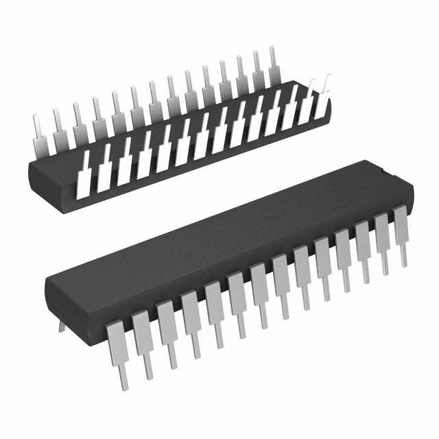
Package
The PIC18F2520-I/SP is available in a 28-pin plastic dual inline package (DIP).
Essence
This microcontroller combines advanced features and low power consumption, making it suitable for a wide range of applications.
Packaging/Quantity
The PIC18F2520-I/SP is typically sold in reels or tubes, with each containing a specific quantity of microcontrollers.
Specifications
- Architecture: 8-bit
- CPU Speed: Up to 40 MHz
- Program Memory Size: 32 KB
- RAM Size: 1536 bytes
- ADC Resolution: 10-bit
- Number of I/O Pins: 22
- Operating Voltage Range: 2.0V to 5.5V
- Temperature Range: -40°C to +125°C
Detailed Pin Configuration
The PIC18F2520-I/SP has a total of 28 pins, each serving a specific purpose. The pin configuration is as follows:
- VDD - Power supply voltage
- RA0 - General-purpose I/O pin
- RA1 - General-purpose I/O pin
- RA2 - General-purpose I/O pin
- RA3 - General-purpose I/O pin
- RA4 - General-purpose I/O pin
- RA5 - General-purpose I/O pin
- VSS - Ground
- OSC1/CLKIN - Oscillator input
- OSC2/CLKOUT - Oscillator output
- RC0 - General-purpose I/O pin
- RC1 - General-purpose I/O pin
- RC2 - General-purpose I/O pin
- RC3 - General-purpose I/O pin
- RC4 - General-purpose I/O pin
- RC5 - General-purpose I/O pin
- RB0/INT0 - External interrupt input
- RB1/INT1 - External interrupt input
- RB2/INT2 - External interrupt input
- RB3/INT3 - External interrupt input
- RB4 - General-purpose I/O pin
- RB5 - General-purpose I/O pin
- RB6 - General-purpose I/O pin
- RB7 - General-purpose I/O pin
- RB8 - General-purpose I/O pin
- RB9 - General-purpose I/O pin
- RB10 - General-purpose I/O pin
- RB11 - General-purpose I/O pin
Functional Features
The PIC18F2520-I/SP offers a range of functional features, including:
- Enhanced Flash program memory for storing code
- Integrated analog-to-digital converter (ADC) for precise measurement of analog signals
- Multiple communication interfaces (UART, SPI, I2C) for data exchange with other devices
- Timers and PWM modules for accurate timing control and generation of analog signals
- Interrupt capability for handling time-critical events
- Power-saving modes to minimize energy consumption
- Built-in oscillator circuitry for generating clock signals
Advantages and Disadvantages
Advantages
- High-performance microcontroller with a wide range of features
- Low power consumption for energy-efficient applications
- Ample program memory and RAM for complex tasks
- Integrated analog-to-digital converter simplifies sensor interfacing
- Multiple communication interfaces enable seamless connectivity
Disadvantages
- Limited I/O pins may restrict the number of external devices that can be connected directly
- 8-bit architecture may not be suitable for computationally intensive applications
Working Principles
The PIC18F2520-I/SP operates based on the principles of a microcontroller. It executes instructions stored in its program memory, interacts with peripherals, and responds to external events through interrupts. The central processing unit (CPU) fetches instructions, decodes them, and performs the necessary operations. The microcontroller's functional features, such as timers, ADC, and communication interfaces, enable it to perform specific tasks according to the programmed instructions.
Detailed Application Field Plans
The PIC18F2520-I/SP finds applications in various fields, including:
- Industrial Automation: Control systems, motor control, and monitoring devices.
- Consumer Electronics: Home appliances, remote controls, and audio/video equipment.
- Automotive:
Перечислите 10 распространенных вопросов и ответов, связанных с применением PIC18F2520-I/SP в технических решениях.
Question: What is the maximum operating frequency of PIC18F2520-I/SP?
Answer: The maximum operating frequency of PIC18F2520-I/SP is 40 MHz.Question: What are the key features of PIC18F2520-I/SP?
Answer: PIC18F2520-I/SP features include 32 KB Flash program memory, 1536 bytes of data memory (RAM), and 256 bytes of EEPROM data memory.Question: Can PIC18F2520-I/SP be used for motor control applications?
Answer: Yes, PIC18F2520-I/SP can be used for motor control applications with its integrated PWM modules and analog-to-digital converters.Question: What communication interfaces are supported by PIC18F2520-I/SP?
Answer: PIC18F2520-I/SP supports USART, SPI, and I2C communication interfaces.Question: Is PIC18F2520-I/SP suitable for battery-powered applications?
Answer: Yes, PIC18F2520-I/SP is suitable for battery-powered applications due to its low power consumption and sleep modes.Question: Can PIC18F2520-I/SP be programmed in C language?
Answer: Yes, PIC18F2520-I/SP can be programmed in C language using MPLAB XC8 compiler.Question: What development tools are available for PIC18F2520-I/SP?
Answer: Development tools such as MPLAB X IDE and PICkit programmers are available for PIC18F2520-I/SP.Question: Does PIC18F2520-I/SP have built-in analog-to-digital converters?
Answer: Yes, PIC18F2520-I/SP has 10-bit analog-to-digital converters.Question: Can PIC18F2520-I/SP be used in industrial automation applications?
Answer: Yes, PIC18F2520-I/SP can be used in industrial automation applications due to its robust design and peripheral integration.Question: What is the temperature range for operating PIC18F2520-I/SP?
Answer: PIC18F2520-I/SP can operate within a temperature range of -40°C to 125°C.