

Подробную информацию о продукте см. в характеристиках.
Encyclopedia Entry: 74AC521PC
Product Overview
Category
The 74AC521PC belongs to the category of integrated circuits (ICs).
Use
This IC is commonly used in digital electronic systems for various applications such as data storage, address decoding, and multiplexing.
Characteristics
- The 74AC521PC is a high-speed, low-power octal latch with transparent outputs.
- It operates on a wide voltage range, typically between 2V and 6V.
- This IC offers excellent noise immunity and high-speed performance.
- It is designed to be compatible with both TTL and CMOS logic families.
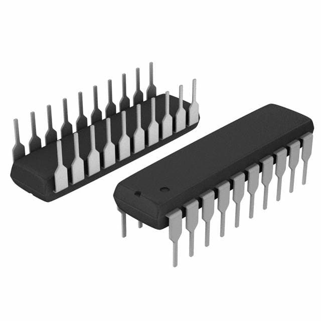
Package
The 74AC521PC is available in a 20-pin plastic dual in-line package (DIP).
Essence
The essence of the 74AC521PC lies in its ability to store and manipulate digital information efficiently within electronic systems.
Packaging/Quantity
This IC is typically sold in reels or tubes containing multiple units. The exact quantity may vary depending on the supplier.
Specifications
- Supply Voltage Range: 2V to 6V
- Input Voltage Range: 0V to VCC
- Output Voltage Range: 0V to VCC
- Operating Temperature Range: -40°C to +85°C
- Maximum Clock Frequency: 100 MHz
- Maximum Propagation Delay: 8 ns
Detailed Pin Configuration
The 74AC521PC has a total of 20 pins, each serving a specific function. Here is the detailed pin configuration:
- GND (Ground)
- D0 (Data Input 0)
- D1 (Data Input 1)
- D2 (Data Input 2)
- D3 (Data Input 3)
- D4 (Data Input 4)
- D5 (Data Input 5)
- D6 (Data Input 6)
- D7 (Data Input 7)
- LE (Latch Enable)
- CLK (Clock Input)
- O0 (Output 0)
- O1 (Output 1)
- O2 (Output 2)
- O3 (Output 3)
- O4 (Output 4)
- O5 (Output 5)
- O6 (Output 6)
- O7 (Output 7)
- VCC (Supply Voltage)
Functional Features
The 74AC521PC offers the following functional features:
- Octal latch with transparent outputs: Allows for easy storage and retrieval of digital data.
- Latch Enable (LE) input: Controls the latching operation, enabling or disabling the storage of data.
- Clock (CLK) input: Synchronizes the latching operation with the system clock.
- Data inputs (D0-D7): Accepts the digital data to be stored.
- Output pins (O0-O7): Provide the stored data as output.
Advantages and Disadvantages
Advantages
- High-speed performance: Enables efficient data processing in digital systems.
- Wide voltage range compatibility: Can be used with various logic families.
- Excellent noise immunity: Ensures reliable operation even in noisy environments.
Disadvantages
- Limited number of outputs: The IC provides only eight output pins, which may be insufficient for certain applications.
- Power consumption: Although low-power, it still consumes some energy during operation.
Working Principles
The 74AC521PC operates based on the principle of latch-based storage. When the Latch Enable (LE) input is active, the data present at the Data Inputs (D0-D7) is latched and stored. The stored data can then be accessed through the Output pins (O0-O7). The Clock (CLK) input synchronizes the latching operation with the system clock, ensuring accurate data storage and retrieval.
Detailed Application Field Plans
The 74AC521PC finds applications in various digital electronic systems, including but not limited to:
- Address decoding circuits: Used to decode address signals in memory systems.
- Multiplexing circuits: Enables the selection of multiple inputs for a single output.
- Data storage systems: Stores digital information for later retrieval or processing.
- Control systems: Facilitates the control and manipulation of digital signals.
Detailed and Complete Alternative Models
There are several alternative models available that offer similar functionality to the 74AC521PC. Some notable alternatives include:
- 74HC521: A CMOS version of the IC with similar characteristics and pin configuration.
- 74LS521: A TTL version of the IC, compatible with older logic families.
- CD74AC521: Another variant of the IC from a different manufacturer.
These alternative models can be considered based on specific requirements, compatibility, and availability.
In conclusion, the 74AC521PC
Перечислите 10 распространенных вопросов и ответов, связанных с применением 74AC521PC в технических решениях.
Sure! Here are 10 common questions and answers related to the application of 74AC521PC in technical solutions:
Q: What is the 74AC521PC? A: The 74AC521PC is a high-speed, low-power octal D-type flip-flop with 3-state outputs.
Q: What is the maximum operating frequency of the 74AC521PC? A: The maximum operating frequency of the 74AC521PC is typically around 200 MHz.
Q: What is the purpose of the 3-state outputs in the 74AC521PC? A: The 3-state outputs allow multiple devices to be connected together without causing conflicts or bus contention.
Q: Can the 74AC521PC be used as a counter? A: No, the 74AC521PC is not designed to function as a counter. It is primarily used as a flip-flop for data storage and transfer.
Q: What is the voltage supply range for the 74AC521PC? A: The 74AC521PC operates with a voltage supply range of 2V to 6V.
Q: How many flip-flops are there in the 74AC521PC? A: The 74AC521PC consists of eight individual D-type flip-flops.
Q: Can the 74AC521PC be cascaded to increase the number of flip-flops? A: Yes, multiple 74AC521PCs can be cascaded together to increase the number of flip-flops in a circuit.
Q: What is the typical propagation delay of the 74AC521PC? A: The typical propagation delay of the 74AC521PC is around 6 ns.
Q: Can the 74AC521PC be used in both synchronous and asynchronous applications? A: Yes, the 74AC521PC can be used in both synchronous and asynchronous applications depending on the circuit design.
Q: What are some common applications of the 74AC521PC? A: The 74AC521PC is commonly used in data storage, address decoding, bus interfacing, and other digital logic applications.
Please note that these answers are general and may vary depending on specific circuit designs and requirements.