

Подробную информацию о продукте см. в характеристиках.
Encyclopedia Entry: 74F269SPC
Product Overview
Category
The 74F269SPC belongs to the category of integrated circuits (ICs) and specifically falls under the family of flip-flops.
Use
This product is primarily used in digital electronic systems for storing and manipulating binary data. It serves as a memory element, allowing for sequential logic operations.
Characteristics
- The 74F269SPC is a synchronous, high-speed, quadruple D-type flip-flop.
- It operates on a wide voltage range, typically between 4.5V and 5.5V.
- This IC offers excellent noise immunity and low power consumption.
- It is designed to work with both TTL and CMOS logic families.
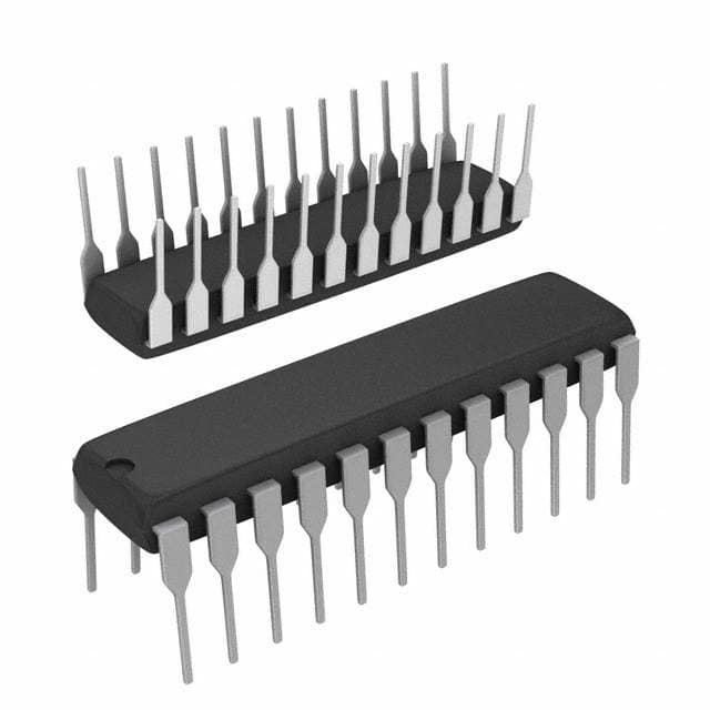
Package and Quantity
The 74F269SPC is available in a 16-pin plastic dual in-line package (DIP). Each package contains one unit of the IC.
Specifications
- Supply Voltage Range: 4.5V to 5.5V
- Operating Temperature Range: -40°C to +85°C
- Maximum Clock Frequency: 100 MHz
- Input Capacitance: 10 pF
- Output Current: ±12 mA
Pin Configuration
The 74F269SPC has a total of 16 pins, each serving a specific function. Here is the detailed pin configuration:
- Clear (CLR)
- Data (D0)
- Data (D1)
- Data (D2)
- Data (D3)
- Clock (CLK)
- Enable (EN)
- Output (Q0)
- Output (Q1)
- Output (Q2)
- Output (Q3)
- Ground (GND)
- Output (Q3')
- Output (Q2')
- Output (Q1')
- Output (Q0')
Functional Features
- The 74F269SPC operates as a positive-edge-triggered D-type flip-flop.
- It has four independent flip-flops, allowing for simultaneous or sequential data storage and retrieval.
- The clear input (CLR) resets all flip-flops to a known state.
- The enable input (EN) controls the clocking of data into the flip-flops.
- The outputs (Q0-Q3) provide the stored data at the corresponding inputs.
Advantages and Disadvantages
Advantages: - High-speed operation enables efficient data processing. - Wide voltage range compatibility allows for versatile integration in various systems. - Excellent noise immunity ensures reliable performance even in noisy environments.
Disadvantages: - Limited number of flip-flops per IC may restrict complex applications. - The 16-pin package size may require additional space on circuit boards.
Working Principles
The 74F269SPC operates based on the principles of sequential logic. When the clock signal transitions from low to high (positive edge), the data present at the inputs (D0-D3) is captured and stored in the flip-flops. The stored data can then be accessed through the output pins (Q0-Q3). The clear input (CLR) resets the flip-flops to a known state, while the enable input (EN) controls the clocking of data.
Application Field Plans
The 74F269SPC finds application in various digital systems, including but not limited to: - Microprocessors and microcontrollers - Data storage devices - Communication systems - Control units - Arithmetic logic units
Alternative Models
For those seeking alternatives to the 74F269SPC, the following models offer similar functionality: - 74LS273 - 74HC273 - CD4013 - SN74LS175
These alternative models can be considered based on specific requirements and compatibility with the existing system.
In conclusion, the 74F269SPC is a versatile flip-flop IC that offers high-speed operation, wide voltage range compatibility, and excellent noise immunity. Its application spans across various digital systems, making it an essential component in modern electronics.
Word Count: 550
Перечислите 10 распространенных вопросов и ответов, связанных с применением 74F269SPC в технических решениях.
Sure! Here are 10 common questions and answers related to the application of 74F269SPC in technical solutions:
Q: What is the 74F269SPC? A: The 74F269SPC is a quad 4-bit binary counter with asynchronous reset, commonly used in digital circuits.
Q: What is the maximum clock frequency supported by the 74F269SPC? A: The maximum clock frequency supported by the 74F269SPC is typically around 100 MHz.
Q: How many bits does the 74F269SPC have? A: The 74F269SPC is a 4-bit binary counter, meaning it has four output bits that can represent numbers from 0 to 15.
Q: Can the 74F269SPC be used as a frequency divider? A: Yes, the 74F269SPC can be used as a frequency divider by connecting the desired clock signal to the input and using the appropriate outputs.
Q: Does the 74F269SPC have an asynchronous reset feature? A: Yes, the 74F269SPC has an asynchronous reset input that allows you to reset the counter to a specific value at any time.
Q: What is the power supply voltage range for the 74F269SPC? A: The 74F269SPC typically operates with a power supply voltage range of 4.5V to 5.5V.
Q: Can the 74F269SPC be cascaded to create larger counters? A: Yes, multiple 74F269SPC chips can be cascaded together to create larger counters with more bits.
Q: What is the propagation delay of the 74F269SPC? A: The propagation delay of the 74F269SPC is typically around 10 ns.
Q: Can the 74F269SPC be used in both synchronous and asynchronous applications? A: Yes, the 74F269SPC can be used in both synchronous and asynchronous applications depending on the requirements of the circuit.
Q: Are there any specific precautions to consider when using the 74F269SPC? A: It is important to ensure proper decoupling capacitors are used near the power supply pins to minimize noise and voltage fluctuations. Additionally, care should be taken to avoid exceeding the maximum ratings specified in the datasheet, such as voltage and temperature limits.
Please note that the answers provided here are general and may vary depending on the specific implementation and datasheet of the 74F269SPC.