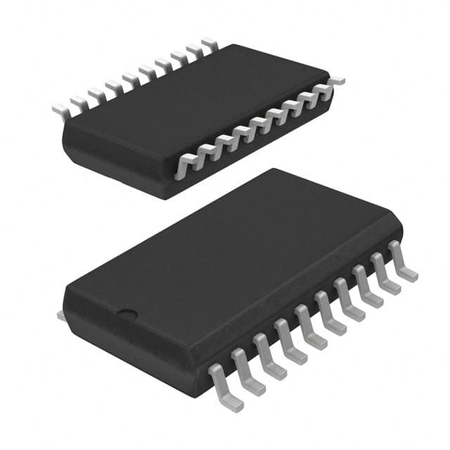
Подробную информацию о продукте см. в характеристиках.

MC74AC574DWR2G
Product Overview
- Category: Integrated Circuit
- Use: Flip-Flop
- Characteristics: High-speed, low-power consumption
- Package: SOIC-20
- Essence: Digital Logic IC
- Packaging/Quantity: Tape and Reel, 2500 units per reel
Specifications
- Logic Family: AC
- Number of Bits: 8
- Operating Voltage: 2V to 6V
- Propagation Delay: 7 ns (typical)
- Operating Temperature Range: -40°C to +85°C
Detailed Pin Configuration
The MC74AC574DWR2G has a total of 20 pins. The pin configuration is as follows:
- Pin 1: Data Input D0
- Pin 2: Data Input D1
- Pin 3: Data Input D2
- Pin 4: Data Input D3
- Pin 5: Data Input D4
- Pin 6: Data Input D5
- Pin 7: Data Input D6
- Pin 8: Data Input D7
- Pin 9: Clock Input CP
- Pin 10: Output Enable Input OE
- Pin 11: Master Reset Input MR
- Pin 12: Q0 Output
- Pin 13: Q1 Output
- Pin 14: Q2 Output
- Pin 15: Q3 Output
- Pin 16: Q4 Output
- Pin 17: Q5 Output
- Pin 18: Q6 Output
- Pin 19: Q7 Output
- Pin 20: Ground (GND)
Functional Features
The MC74AC574DWR2G is an 8-bit flip-flop integrated circuit. It operates on a wide voltage range and offers high-speed performance with low power consumption. The device features a master reset input, which allows for resetting all the flip-flops simultaneously. It also has an output enable input that can be used to disable the outputs when needed.
Advantages and Disadvantages
Advantages: - High-speed operation - Low power consumption - Wide operating voltage range - Master reset functionality
Disadvantages: - Limited number of bits (8) - Not suitable for applications requiring higher bit counts
Working Principles
The MC74AC574DWR2G is based on flip-flop logic, specifically D-type flip-flops. It stores and transfers data in sequential order based on clock signals. The inputs (D0-D7) are latched and stored when a rising edge is detected on the clock input (CP). The stored data can then be accessed from the corresponding output pins (Q0-Q7).
Detailed Application Field Plans
The MC74AC574DWR2G is commonly used in various digital systems and applications, including but not limited to: - Data storage and transfer systems - Register banks - Address decoding circuits - State machines - Control units
Detailed and Complete Alternative Models
- SN74AC574DW - Similar specifications and pin configuration, different manufacturer (Texas Instruments)
- CD74AC574E - Similar specifications and pin configuration, different package type (PDIP-20)
- 74HC574N - Different logic family (HC), similar specifications and pin configuration
These alternative models provide similar functionality and can be used as replacements for the MC74AC574DWR2G depending on specific requirements and availability.
Word count: 334 words
Перечислите 10 распространенных вопросов и ответов, связанных с применением MC74AC574DWR2G в технических решениях.
Sure! Here are 10 common questions and answers related to the application of MC74AC574DWR2G in technical solutions:
Q: What is MC74AC574DWR2G? A: MC74AC574DWR2G is a type of integrated circuit (IC) commonly used as an octal D-type flip-flop with 3-state outputs.
Q: What are the key features of MC74AC574DWR2G? A: Some key features include high-speed operation, wide operating voltage range, 3-state outputs, and compatibility with TTL inputs.
Q: How can MC74AC574DWR2G be used in technical solutions? A: It can be used for data storage, synchronization, and signal buffering in various digital systems and applications.
Q: What is the maximum operating frequency of MC74AC574DWR2G? A: The maximum operating frequency is typically around 100 MHz.
Q: What is the power supply voltage range for MC74AC574DWR2G? A: The power supply voltage range is usually between 2V and 6V.
Q: Can MC74AC574DWR2G handle both rising and falling edge-triggered inputs? A: Yes, it can handle both rising and falling edge-triggered inputs.
Q: Does MC74AC574DWR2G have any built-in protection features? A: Yes, it has built-in diode clamps to minimize the effects of electrostatic discharge (ESD).
Q: Can MC74AC574DWR2G drive high capacitive loads? A: Yes, it has a high output drive capability that allows it to drive relatively high capacitive loads.
Q: Is MC74AC574DWR2G compatible with other logic families? A: Yes, it is compatible with both TTL and CMOS logic families.
Q: What is the package type for MC74AC574DWR2G? A: MC74AC574DWR2G is available in a 20-pin SOIC (Small Outline Integrated Circuit) package.
Please note that these answers are general and may vary depending on the specific datasheet and manufacturer's specifications for MC74AC574DWR2G.

