

Подробную информацию о продукте см. в характеристиках.
74AUC1G125DBVRE4
Basic Information Overview
- Category: Integrated Circuit (IC)
- Use: Buffer/Driver
- Characteristics: Single Gate, Non-Inverting, Tri-State Output
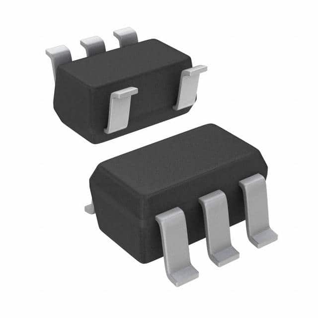
- Package: SOT-23-5
- Essence: High-Speed CMOS Logic
- Packaging/Quantity: Tape and Reel, 3000 pieces per reel
Specifications
- Supply Voltage Range: 0.8V to 3.6V
- Input Voltage Range: 0V to VCC
- Output Voltage Range: 0V to VCC
- Maximum Operating Frequency: 500MHz
- Propagation Delay: 2.5ns (typical)
- Output Current: ±24mA
- Operating Temperature Range: -40°C to +85°C
Detailed Pin Configuration
The 74AUC1G125DBVRE4 IC has a total of 5 pins arranged as follows:
____
   OE --|    |-- VCC
   A  --|    |-- Y
  GND --|____|-- B
Functional Features
- Tri-State Output: The output pin (Y) can be put into a high-impedance state by controlling the output enable pin (OE).
- Non-Inverting: The input signal (A) is directly passed to the output (Y) without any inversion.
- High-Speed Operation: This IC is designed for high-speed CMOS logic applications, allowing fast data transmission.
Advantages and Disadvantages
Advantages: - Low Power Consumption: Operates at low supply voltages, resulting in reduced power consumption. - Small Package Size: The SOT-23-5 package offers a compact form factor, making it suitable for space-constrained designs. - Wide Operating Temperature Range: Can operate reliably in extreme temperature conditions.
Disadvantages: - Limited Output Current: The maximum output current is ±24mA, which may not be sufficient for driving certain loads. - Single Gate: This IC contains only one logic gate, limiting its functionality compared to multi-gate ICs.
Working Principles
The 74AUC1G125DBVRE4 is a buffer/driver IC that amplifies and buffers digital signals. It operates based on high-speed CMOS logic principles, where the input signal (A) is amplified and passed through a non-inverting buffer stage. The output (Y) can be enabled or disabled using the output enable pin (OE), allowing control over the signal transmission.
Detailed Application Field Plans
The 74AUC1G125DBVRE4 IC finds applications in various fields, including but not limited to: 1. Communication Systems: Used for signal buffering and level shifting in data communication interfaces. 2. Industrial Automation: Enables signal amplification and isolation in industrial control systems. 3. Consumer Electronics: Suitable for use in portable devices, such as smartphones and tablets, due to its low power consumption and small package size. 4. Automotive Electronics: Used in automotive systems for signal conditioning and interfacing between different components.
Detailed and Complete Alternative Models
Some alternative models that offer similar functionality to the 74AUC1G125DBVRE4 IC include: - SN74LVC1G125DBVR - MC74VHC1G125DTT1G - TC7SZ125FU
These alternatives provide comparable features and can be used as replacements depending on specific design requirements.
Word count: 411
Перечислите 10 распространенных вопросов и ответов, связанных с применением 74AUC1G125DBVRE4 в технических решениях.
Sure! Here are 10 common questions and answers related to the application of 74AUC1G125DBVRE4 in technical solutions:
Q1: What is the 74AUC1G125DBVRE4? A1: The 74AUC1G125DBVRE4 is a single bus buffer gate with 3-state output, designed for low-voltage applications.
Q2: What is the operating voltage range of the 74AUC1G125DBVRE4? A2: The operating voltage range of the 74AUC1G125DBVRE4 is from 0.8V to 3.6V.
Q3: What is the maximum output current of the 74AUC1G125DBVRE4? A3: The maximum output current of the 74AUC1G125DBVRE4 is 32mA.
Q4: Can the 74AUC1G125DBVRE4 be used in high-speed applications? A4: Yes, the 74AUC1G125DBVRE4 is suitable for high-speed applications due to its fast propagation delay and transition times.
Q5: Does the 74AUC1G125DBVRE4 have internal pull-up or pull-down resistors? A5: No, the 74AUC1G125DBVRE4 does not have internal pull-up or pull-down resistors.
Q6: Can the 74AUC1G125DBVRE4 be used as a level shifter? A6: Yes, the 74AUC1G125DBVRE4 can be used as a level shifter between different voltage domains.
Q7: Is the 74AUC1G125DBVRE4 compatible with other logic families? A7: Yes, the 74AUC1G125DBVRE4 is compatible with a wide range of logic families, including CMOS, TTL, and LVCMOS.
Q8: What is the package type of the 74AUC1G125DBVRE4? A8: The 74AUC1G125DBVRE4 is available in a small SOT-23 package.
Q9: Can the 74AUC1G125DBVRE4 be used in battery-powered applications? A9: Yes, the 74AUC1G125DBVRE4 is suitable for battery-powered applications due to its low power consumption.
Q10: Are there any special considerations when using the 74AUC1G125DBVRE4 in high-frequency applications? A10: In high-frequency applications, it is important to consider the PCB layout and minimize parasitic capacitance and inductance for optimal performance.
Please note that these answers are general and may vary depending on specific application requirements.